
Navigation Device
Making a Navigation Device with GPS and an IMU
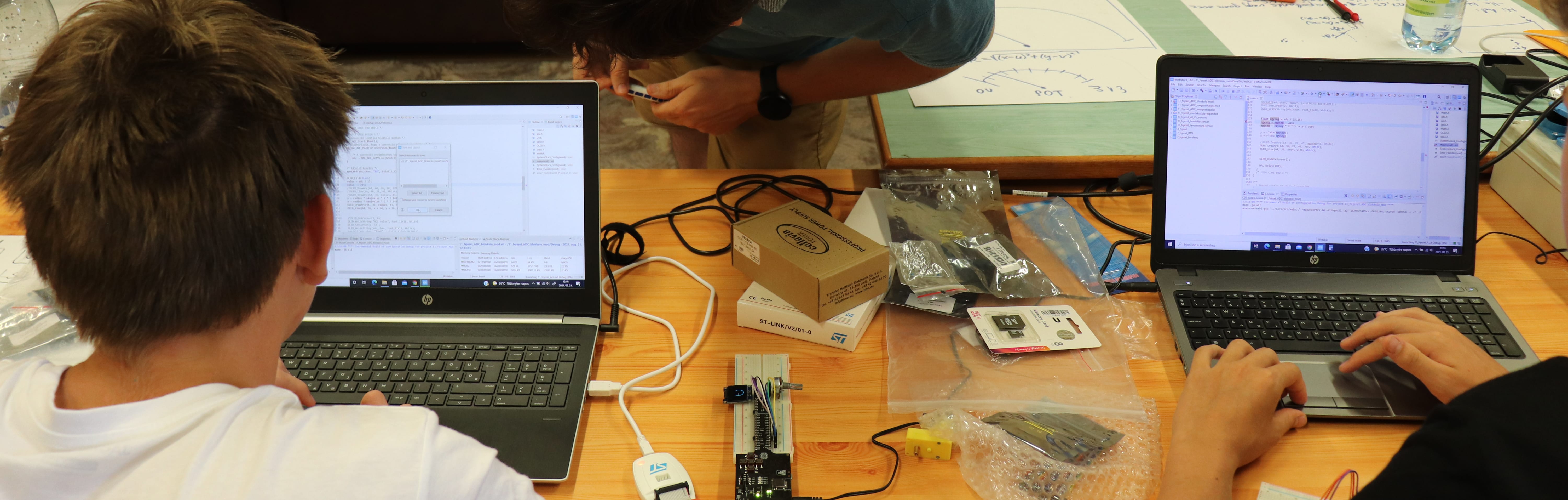
For the 2025 Crystal Celar Electronics summer camp, we designed a custom circuit containing a GPS module and an IMU (Inertial Measurement Unit) to provide advanced students with a unique hands-on task. The GPS module on the board can determine the current geographic position by processing data from positioning satellites, while the IMU uses internal MEMS sensors to measure angular velocity, acceleration, and detect the surrounding magnetic field. Using the magnetometer in the IMU, it is possible to calculate the direction of north. The students’ task is to utilize the knowledge gained in CCE2 and the capabilities of the circuit to independently, but with professional guidance, create the most practical smart navigation device possible. Brief description of the main tasks:
1. Task – Display deviation from the north direction
Read data from the ICM-20948 magnetometer and display the deviation from the north-south direction on the screen in degrees, draw a compass. Data can be read via I2C, and the IC must be properly initialized beforehand. The KE2 I2C chapters and the sensor datasheet provide guidance for this.
2. Task – Determine location using the GPS module
Implement communication with the CAM-M8 U-blox GPS receiver via UART and display the received latitude and longitude coordinates on the screen. The CCE2 UART chapters and the module’s datasheet and description provide assistance.
3. Task – Determine distance and direction from a pre-programmed point
Store the coordinates of the target point (hard-coded) in the microcontroller’s software. Using the data acquired in the previous tasks, calculate and display on the screen the current distance from the target in meters and the deviation of the current heading from the target direction in degrees.
The project’s files, design documents, bill of materials, programming guide, and example implementation source code are available here:
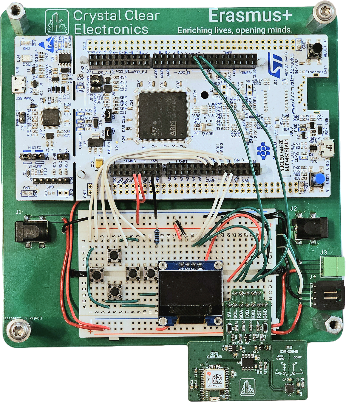
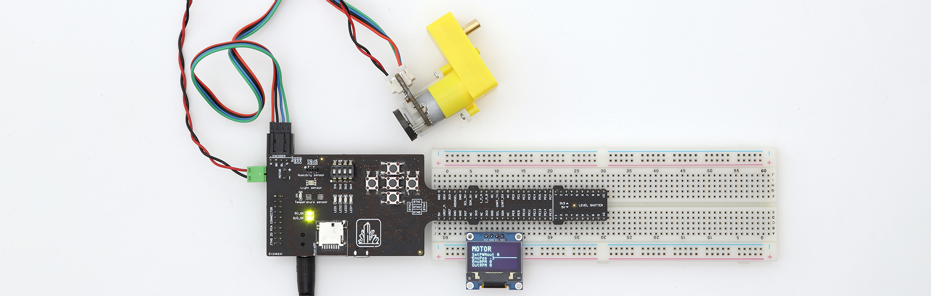
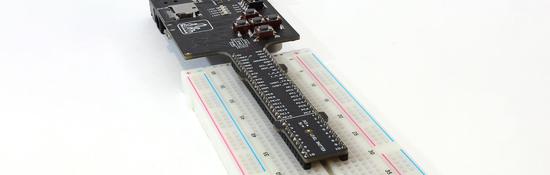
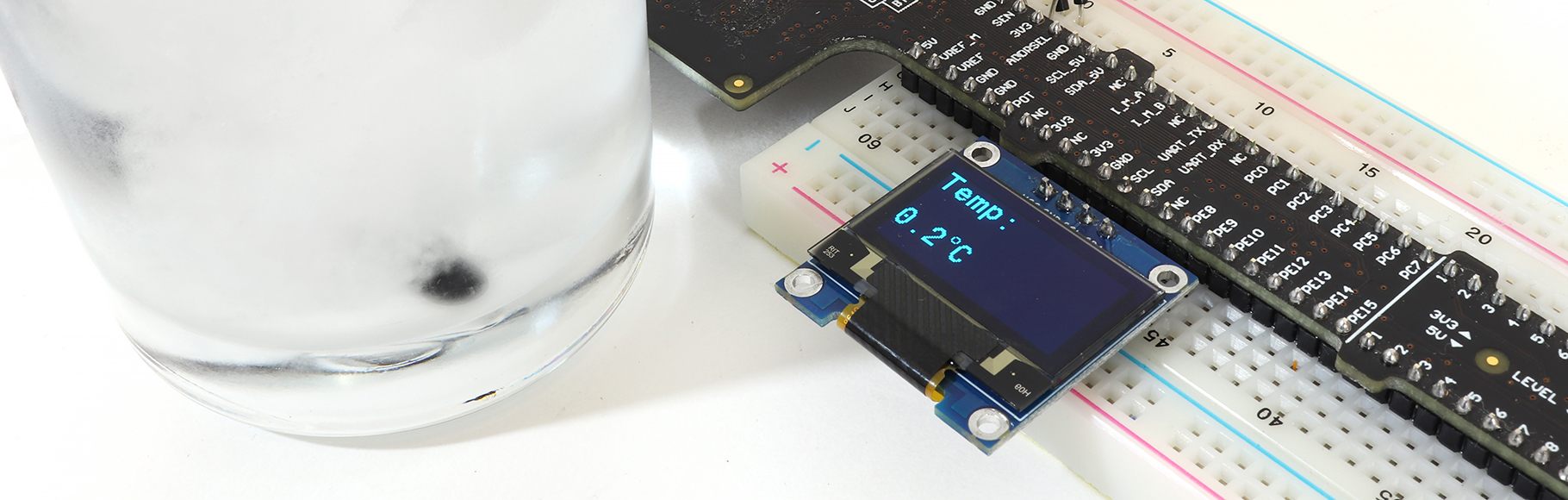
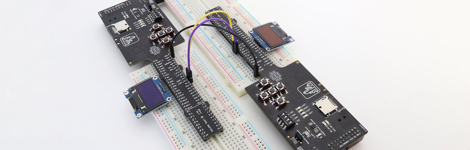
The picture below shows an example setup, consisting of a Nucleo board, 5 push buttons, 1 display, and the GPS-IMU board. The push buttons and display are connected the same way as in the curriculum examples, with the exception that no I2C pull-up resistors need to be placed on the breadboard, since the GPS-IMU board already contains them.
The GPS-IMU board connections are as follows:
- 5V: Power supply – connect the Nucleo’s 5 V supply here
- SCL, SDA: Connect these to the I2C lines used for the display
- TXD, RXD: The GPS module’s UART TX and RX lines – connect them to the RX and TX lines of a free UART peripheral on the microcontroller (we used UART6) (connect RX of one device to TX of the other)
- GND: Common ground